NAGFORM is a rule based software program for automatic and manual design of forming sequence for cold forged parts. The sequence designs created in NAGFORM can be tested effortlessly in NAGSIM.2D/3D FEA simulation software. NAGFORM can be used to:
- Obtain alternative sequence designs in a few minutes
- Create reusable sequence-design templates
- Create ‘Generic’ tooling around a sequence
- Create DXF & SolidWorks output of sequence designs
- Reduce number of forming operations
- Obtain estimated loads, pressures and deformation
- Select machines for a sequence from a machine database
- Automatically get dimensions, volume and surface area of the parts

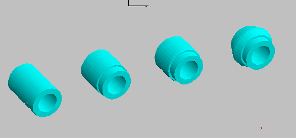
Automatic Design of Forming Progression in Minutes – NAGFORM utilizes a combination of design logic, knowledge-based rules and simplified analyses to determine alternative forming progression automatically.
Progression Design Concepts – Because the program looks for all possible designs and applies its logic without fail, NAGFORM can come up with design concepts that even experienced designers may overlook.
Template Designs for ‘Family of Parts’ – For any part that is similar to a template in the database, NAGFORM can follow the template design/session files to create forming progressions in minutes. The users have the capability to create their own reusable template designs.
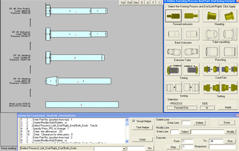
Design by Command – ‘Design by Command’ allows the user to create their own design progression interactively in a few minutes. The interactive session is saved in a file. This session file can be used as a template to create progression design for similar parts or family of parts in minutes.
Manual Design – NAGFORM also has a separate module for creating a forming progression manually. Using computer aided techniques, the user can quickly and easily construct a forming sequence according to his/her concept. The designer can also start from a NAGFORM generated design and modify it.
Built a Historic ‘Part & Template Design’ Database – In NAGFORM, any part and its progression design can be stored as a ‘Design Template’. Over time, a company can built a database of parts and their successful designs.
Design of Tool Components and Assemblies – The designer can manually create tooling components and assemblies using templates and modeling capabilities of NAGFORM. Any component can be stored as a template for later use.
Automatic Creation of ‘Default’ Tooling – For most of the sequence designs obtained through NAGFORM logic, ‘Generic’ tooling can be created automatically.
Automatic Creation of Analysis File for Simulation in NAGSIM.2D – The forming sequence and the ‘Generic’ tooling is used to create an analysis file automatically for simulation in NAGSIM.2D FEA program. This saves hours of human effort to perform FEA simulation.
NAGFORM – SolidWorks Interface – All Parts, Designs, Default Tooling and Tooling Components can be automatically exported into a SolidWorks part drawing. Click on link for more detail.
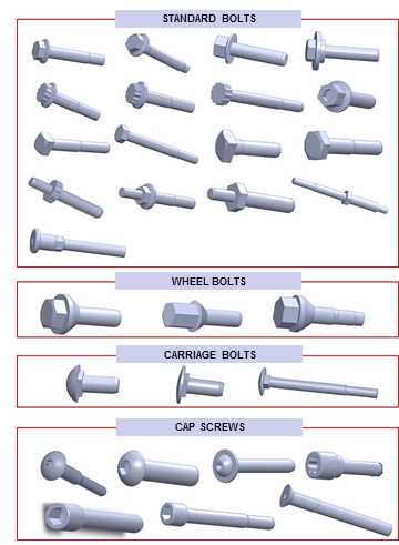
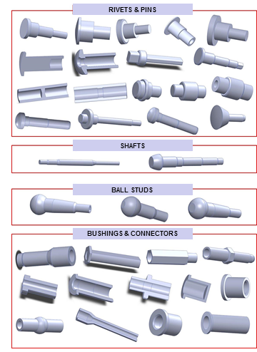
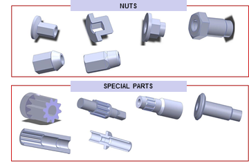
Available Templates – Parts and Designs
NAGFORM/Sheet is a knowledge based software program for designing forming sequence of sheet metal parts. It allows the user to capture manufacturing knowledge and use it to design forming progressions for similar parts in minutes. The sequence designs created in NAGFORM/Sheet can be quickly validated in NAGSIM.2D / NAGSIM.3D FEA simulation programs. It is available as a stand-alone software or as an add-on module with NAGFORM software program. The advantage of NAGFORM program with this module is that the user can compare the manufacturing steps for parts that can be cold forged from solid as well as formed from sheet. This can help in converting sheet metal parts to cold forged parts and vice versa.
Uses-
- Determine material required, surface area and weight of formed part.
- Create sequence design for forming a part, in minutes.
- Save any automatic design as a reusable design template.
- Search for knowledge on similar parts in design database
- Obtain estimated forming loads and pressures.
- Create analysis file for NAGSIM.2D / NAGSIM.3D for design validation
Limitations:
NAGFORM/Sheet is not a FEA simulation program. It cannot predict metal flow defects and stresses in tools.
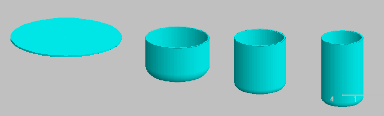
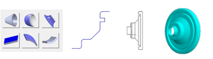
Create Part Model
In NAGFORM/Sheet, Geometric model of a part is constructed by joining simple building blocks called primitives. Based on the part dimensions and material, the program determines the Volume, Surface Area, and Weights. Complex parts can be created and designed using these primitives. The user can also create a sheet metal part model from a sketch created within NAGFORM or imported from a 2D Dxf drawing.
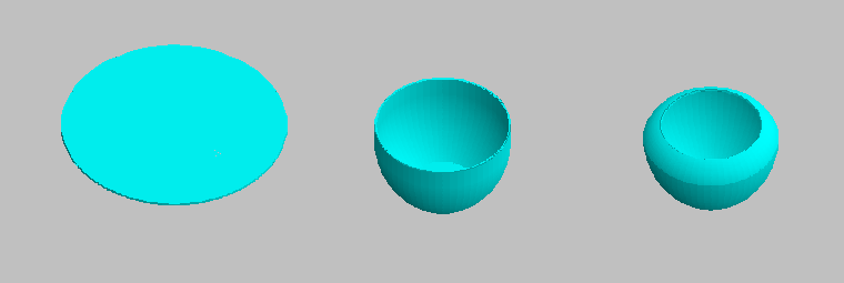
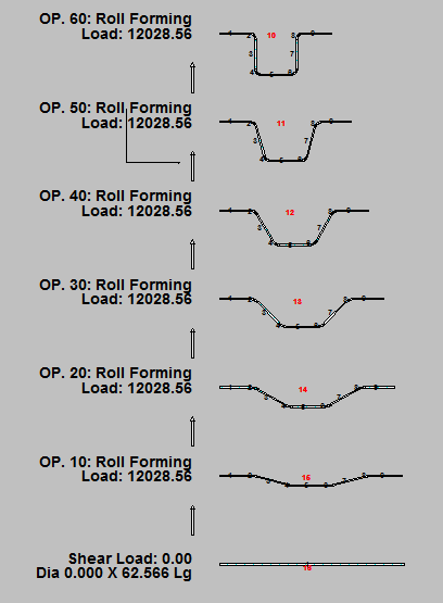
Automatic Designs of Forming Progressions
NAGFORM/Sheet utilizes a combination of design logic, knowledge based rules and simplified analyses to determine a forming progression automatically in minutes. In general, there is more than one forming sequence by which a part can be formed. The number of designs depends upon part geometry and, material being formed. NAGFORM/Sheet has its own design logic to determine various possible ways to form a part. Because the program looks for all possible designs and applies its logic without fail, NAGFORM/Sheet can determine design concepts that even an experienced designer may overlook.
 fff
fff 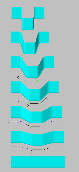 fff
fff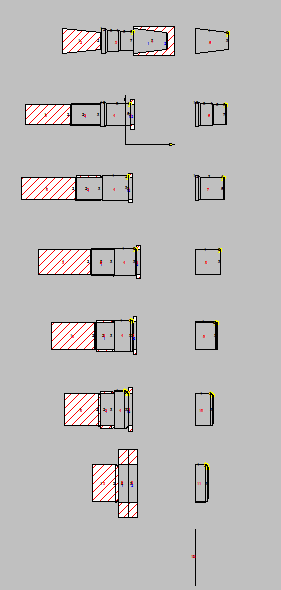
Template Designs for ‘Similar Parts’ or ‘Family of Parts’
For any part that is similar to a template in the database, NAGFORM/Sheet can follow the template design files to create forming progressions in minutes. The users have the capability to create their own reusable template designs.
DXF Input and Output
In NAGFORM/Sheet, the geometry of parts can also be imported from DXF format from CAD systems such as AutoCAD, SolidEdge etc. The results of NAGFORM/Sheet sequence designs and ‘Generic’ tooling can be saved in DXF format for input to other CAD systems.
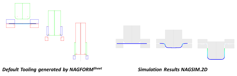
Generic Tooling for FEA Simulation
For the sequence designs obtained through NAGFORM/Sheet logic, ‘Generic’ tooling can be created automatically. This generic tooling can be used to simulate the forming operation in a FEA simulation program such as ‘NAGSIM.2D’ and ‘NAGSIM.3D’.
Integration with NAGSIM.2D
In NAGFORM/Sheet, simulation files for NAGSIM.2D can be automatically created for any selected part progression generated in Auto Design. To simulate, the user opens this file in NAGSIM.2D, meshes the parts and begins simulating. It takes only couple of minutes to go from NAGFORM’s design concept to NAGSIM.2D simulation.
Manual Design
In addition to automatic design, NAGFORM/Sheet has a separate module for creating a forming progression manually. Using computer aided techniques, the user can quickly and easily construct a forming sequence according to his/her concept. The designer can also start from a NAGFORM/Sheet generated design and modify it.
NAGFORM + NAGFORM/Sheet Module
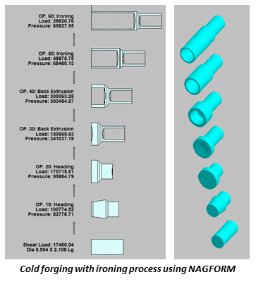
This option allows full capabilities of NAGFORM program with additional capabilities of NAGFORM/Sheet module. User can design forging sequence for cold forged part as well as design forming sequence for sheet metal parts. In certain cases, sheet forming processes such as ‘Ironing’ to reduce part thickness and ‘Drawing’ to reduce outside diameter of thin section can be combined with cold forging processes to manufacture parts with thick and thin sections. Examples of such parts are ammunition shells and high pressure cylinders. Following are some additional features of the NAGFORM + NAGFORM/Sheet program:
• Perform comparative study of parts that can be made from sheet metal as well as wire/rod
• Help in converting sheet metal parts to cold forged part and vice versa
• Help in eliminating welding in assembly of sheet metal part with thick / solid parts
Nagforge is a knowledge based software program for automatic and manual design of forging sequence for hot and warm forged parts. It allows the User to capture manufacturing knowledge and use it to design progressions for similar parts.
NagForge utilizes a combination of design logic, knowledge-based rules and simple analyses to determine a forging progression automatically in minutes.The sequence designs created in NagForge can be tested effortlessly in NAGSIM_Gen.2D FEA simulation software.
Uses:
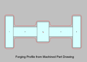
- Create hot forging part profile from machined part profile.
- Obtain alternative sequence designs for forging a part in a few minutes.
- Calculate flash dimensions for closed die forgings.
- Create reusable sequence-design templates of your own designs or designs from NagForge.
- Automate and standardize sequence design of similar parts.
- Create DXF output of sequence designs in a few minutes
- Select optimal blank diameter
- Reduce number of forming operations
- Obtain estimated loads, pressures and deformation
Limitations: NagForge is not a FEA simulation program. It can not predict metal-flow defects and stress distribution in tools. Nagforge can be used only for parts with some symmetry such as parts made on upsetters and closed die forgings. Parts can have features such as polygons, flats and splines.
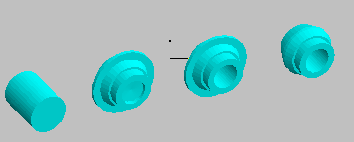
Alternative Forming Progressions in Minutes – NagForge has its own design logic to determine various possible ways a part can be formed. Because the program looks for all possible designs and applies its logic without fail, NagForge can come up with design concepts that even experienced designers may overlook.
Template Designs for ‘Family of Parts’ – For any part that is similar to a template in the database, NagForge can follow the template design / session file to create forming progression in minutes.
Manual Design – In addition to automatic design, NagForge has a separate module for creating a forming progression manually. Using computer aided techniques, the user can quickly construct a forming sequence according to his/her own concept. The designer can also start from a computer-generated design and modify it.
DXF Input and Output – In NagForge, a part is constructed using simple shapes called primitives. The geometry of parts can also be imported from CAD systems such as AutoCad. The NagForge output including sequence designs can be saved in DXF format for input to other CAD systems.
Forging Profile from Machined Part Drawing – Nagforge has a separate module for creating Forging Profile from machined part drawing. User can specify machining allowance on outside profile as well as bore. Fillet and corner radii as well as forging draft angles can be specified.